Abstract
The utility model relates to mining equipment, particularly relates to a rolling self-moving machine tail device for a belt feeder. The rolling self-moving machine tail device for a belt feeder comprises a self-moving belt feeder tail and a hydraulic cylinder. The utility model is characterized in that both sides of the self-moving belt feeder tail are permanently provided with a support oil cylinder of which one end is fixed on the self-moving belt feeder tail and the other end is connected with a walking wheel carrier which can be movable arranged on a floor rail which is arranged on a bottom plate; a traction oil cylinder is permanently arranged between the floor rail and the self-moving belt feeder tail. The rolling self-moving machine tail device for a belt feeder overcomes adverse effects generated by the reaction force on the gliding of a reversed loader when moving; the original sliding moving is changed to the rolling moving to enhance the work efficiency of the coal mining machinery.
Description
Conveyor rolling self-movable foot end device
Technical field
The utility model relates to a kind of winning equipment, particularly relates to a kind of conveyor rolling self-movable foot end device.
Background technology
At present, domestic crossing equipment moves the three kinds of forms that mainly contain.First kind of form is that oil cylinder pulling stage loader moves along the ordinary straps tail, generally move 13 meters strokes after, tear the belt middle frame open and manually draw and move belt machine end, this is the most general move mode of domestic use, but labor strength is big, mechanization degree is low.Second kind of form is that oil cylinder pulling stage loader moves along moving belt machine end certainly, and after elevating conveyor moved full stroke, stroke was generally 2.7-3 rice, and belt machine end is again from moving.This form mechanization, automaticity height are progressively accepted by highly efficient and productive mine approval in recent years, produce favorable economic benefit.The third form is that step type is from moving stage loader along moving from moving belt machine end, the product of Lu'an Bureau of Mine introduction NEI company in 1994 adopts this form exactly, owing to cast aside traditional anchoring fully and drawn the mode of moving, less demanding to crossing top board and base plate, therefore very being suitable for the utilization of weak seam, is the highest crossing move mode of present domestic mechanization degree.
Step type from move stage loader and move belt machine end certainly mobile be fulcrum each other, be to produce mobile greater than the frictional force of belt machine end and base plate generation promptly with elevating conveyor and base plate frictional force from moving the mobile of belt machine end, simultaneously, the frictional force that belt machine end and base plate produce reacts to elevating conveyor, and this is totally unfavorable to the crossing haulage device that has 25 ° of crossings to face upward to adopt the inclination angle.
Summary of the invention
The utility model provides a kind of conveyor rolling self-movable foot end device, promptly from moving belt machine end and the same moved further of elevating conveyor, thereby the adverse effect that the reaction force when overcoming belt machine end and moving glides and produces elevating conveyor, original slip is moved become to roll and move, improved the operating efficiency of coal-cutting machinery greatly.
The technical solution of the utility model is: a kind of conveyor rolling self-movable foot end device, comprise from moving belt machine end, hydraulic cylinder, it is characterized in that being installed with support cylinder in the both sides of moving belt machine end certainly, one end of support cylinder is fixed on from moving on the belt machine end, the other end links to each other with the walking wheel carrier, the walking wheel carrier movable is installed in and lands on the guide rail, and the guide rail that lands is installed on the base plate, moves with oneself and is installed with the passing oil cylinder between the belt machine end landing guide rail.
Pass oil cylinder one end by hinge with fix from moving belt machine end, the other end is hinged on and is fixedly installed on the bearing that lands on the guide rail.
The outer slip of support cylinder cylinder body is with fairlead, is socketed with to connect cover outside fairlead, and fairlead links to each other with the piston rod and the walking wheel carrier of support cylinder by hinge, connection cover by hinge and support cylinder cylinder body with move belt machine end certainly and link to each other.
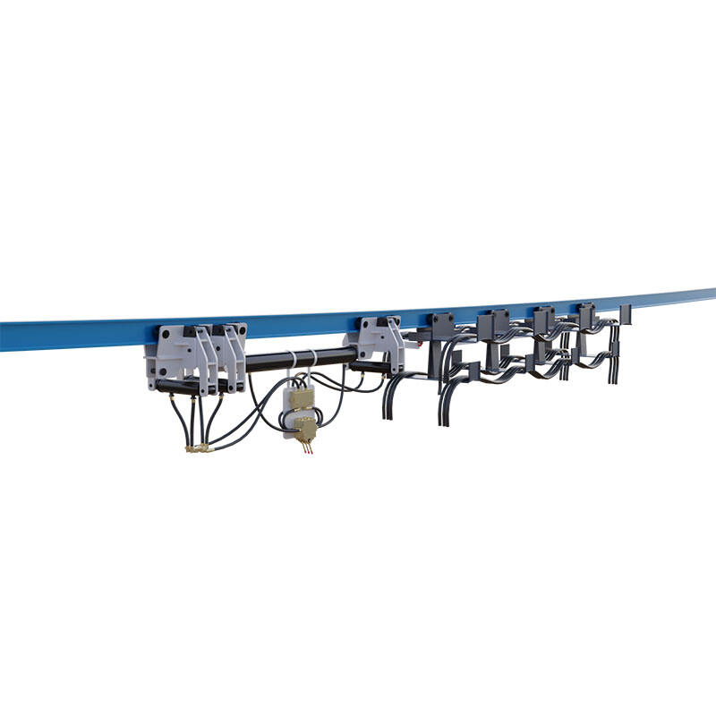
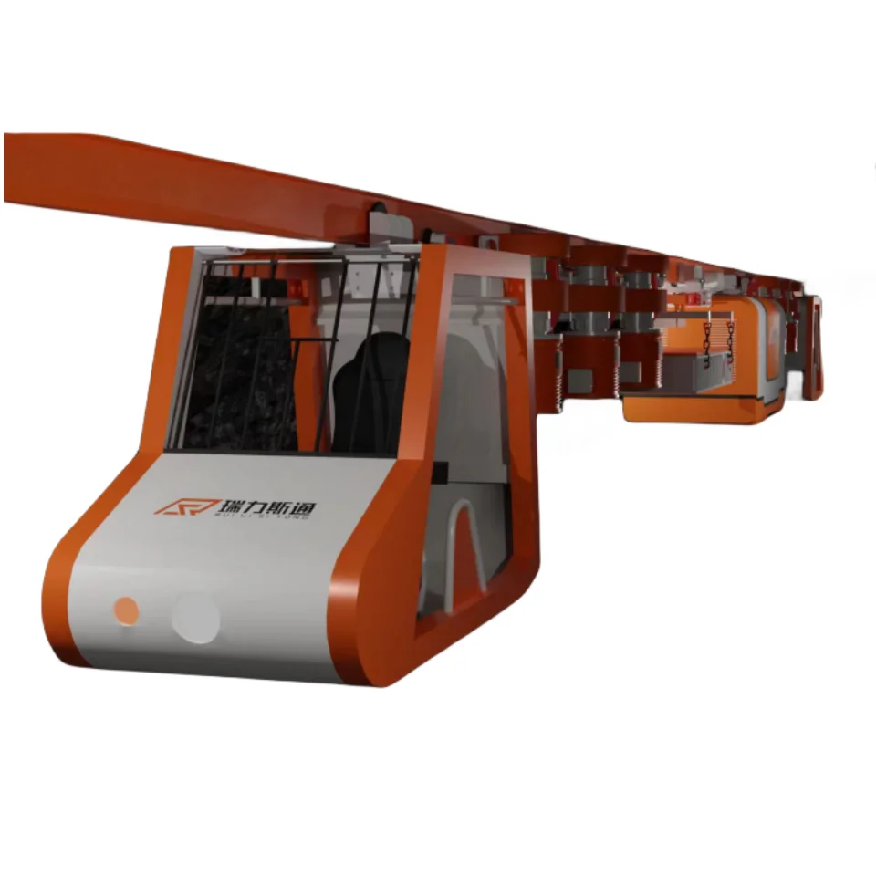
As shown in Figure 1, 2, be installed on the base plate 6 from moving belt machine end 7, on base plate 6, be equipped with and land guide rail 2 from moving the belt machine end both sides, the landing of every side is equipped with two on the guide rail can land the walking wheel carrier 1 that moves on the guide rail, each walking wheel carrier and support cylinder 5 one ends are hinged, and the other end of support cylinder is fixed on from moving on the belt machine end; Between two road wheels that land on the guide rail, be fixed with bearing 3, pass oil cylinder 4 one ends and be fixedly installed on the bearing 3 that lands on the guide rail by being hinged on, the other end with from moving the belt machine end hinge.
The outer slip of support cylinder cylinder body is with fairlead 11, is socketed with to connect cover 9 outside fairlead, and fairlead links to each other with the piston rod and the walking wheel carrier of support cylinder by hinge 12, connection cover by hinge 8 and support cylinder cylinder body 10 with move belt machine end certainly and link to each other.
In use, after four support cylinder oil-feeds that move the belt machine end both sides are certainly risen, will move belt machine end certainly and lift, complete machine weight acts on by the walking wheel carrier lands on the guide rail, makes to land guide rail and certain specific pressure and the friction of base plate generation.At this moment, pass the oil cylinder oil-feed, piston rod promotes from moving belt machine end along landing guide rail rolling reach by hinge, after moving a stroke or appropriate location, the withdrawal of support cylinder piston rod makes from moving belt machine end and falls on the base plate, to land guide rail by the walking wheel carrier simultaneously and lift from base plate, pass the oil cylinder bar plug withdrawal of living, drive and land guide rail and move forward a stroke or appropriate location, just finished once reach by being fixed on the bearing that lands on the guide rail.Fallback procedures and reach process are basic identical.
The piston rod of support cylinder is when stretching out, because it is very big from the weight of moving belt machine end, the coal mining activity face can not be very flat simultaneously, piston rod just will be subjected to the effect of vertical and horizontal resultant force like this, and the fairlead that is enclosed within outside the cylinder body can bear most of horizontal applied force, so just can reduce the distortion of piston rod under the effect of horizontal force, along having grown its application life.
 Hot News
2024-02-18
2024-02-19
2024-02-06

 EN
EN
 AR
AR BG
BG HR
HR CS
CS DA
DA NL
NL FI
FI FR
FR DE
DE EL
EL HI
HI IT
IT JA
JA KO
KO NO
NO PL
PL RU
RU ES
ES TL
TL ID
ID SR
SR SK
SK UK
UK VI
VI HU
HU TH
TH TR
TR MS
MS GA
GA EO
EO LA
LA MN
MN TG
TG UZ
UZ